EQ Wave Installation
Safety Requirements
Installation of the EQ Wave sensor involves direct connection to energized electrical systems and must be performed only by qualified electrical personnel familiar with electrical safety procedures, local electrical codes, and proper lockout/tagout protocols.
Critical Safety Information
Qualified Personnel:
- Electrical contractor license (where required by local jurisdiction)
- Experience with 3-phase power systems up to 600V
- Knowledge of power measurement equipment
- Understanding of NFPA 70E arc flash and electrical safety standards
De-Energization Requirements:
- De-energize all circuits using proper lockout/tagout (LOTO) procedures before making electrical connections
- Follow NFPA 70E or equivalent electrical safety standards
- Use appropriate personal protective equipment (PPE):
- Arc-rated clothing (minimum 8 cal/cm² where required)
- Arc-rated face shield (if working on energized circuits)
- Insulated gloves rated for working voltage
- Safety glasses and hard hat (where required)
Default configuration: Voltage-output current transducers with internal burden resistors (e.g., Socomec Accu-CT, 333mV output).
Do NOT use traditional current transformers (CTs) with default configuration. CTs produce dangerous open-circuit voltages without proper external burden resistors.
Before installation:
- Verify your current sensors are voltage-output transducers (333mV output) OR
- Contact support@eq.systems to configure unit for traditional CTs with external burden resistors
- See detailed current sensor requirements in Step 3 below
Voltage and Power Limits:
- Voltage measurement inputs (V0-V3): 600V RMS maximum (designed to IEC 61010-2-030 CAT III, PD 2, ≤2000m)
- AC power supply terminals (L/L1, N/L2): 528V AC maximum, OVC III
- For systems above 600V line-to-ground, use appropriate potential transformers (PTs)
- For AC power above 528V, use external DC power supply
The measuring inputs are rated 600V; the power input is rated 528V. On a 600V-class system these do not match, and the difference is the installer’s to manage. On 600Y/347, wire the supply phase-to-neutral (347V) — it stays inside the 528V rating. On a 600V delta, where every pair is 600V, do not wire the supply from the measured system; use an external DC supply instead.
Installation Environment:
- Operating temperature: -40°C to +70°C
- Install in electrical enclosure or panel providing appropriate environmental protection
- Maintain clearances per local electrical code requirements
Package Contents
EQ Wave Device Unit:
- Device with serial number EQW-_________ (record for support reference)
-
Mounting hardware (one option, as specified when ordering):
- 3M Dual Lock adhesive strips (standard)
- DIN rail clips (35mm rail, IEC 60715)
- Magnets for ferrous surfaces
- USB power cable (for benchtop testing and configuration)
Communications:
- 2.2mm duplex POF (plastic optical fiber) cable (default 2m length; custom lengths available)
- Media converter (Firecomms FY-ENT-KSU)
- Media converter USB power cable
- Media converter USB power supply (5V, 0.5A)
- POF cutting tool
- Cat5e Ethernet patch cable (RJ45, for media converter to gateway connection)
Installation Materials:
- Self-adhesive cable identification labels
- Alcohol prep pad (surface preparation for adhesive mounting)
Accessories: Additional POF cable and media converter kits (FF-FYENT-KSU, includes media converter, USB power cable, USB power supply, POF cutting tool, and Cat5e patch cable) are available from FiberFin in North America.
Note: The EQ Wave requires a host computer for data collection and configuration. This can be the EQ Gateway (sold as a separate option) or a customer-supplied computer. See Deployment Options for details.
Connection Guide
Step 1: Mount the Device
Mounting Method (as supplied with your kit):
3M Dual Lock Adhesive (standard):
- Clean mounting surface with alcohol prep pad; allow 15 seconds to dry
- Peel protective backing from adhesive strips (pre-applied to sensor enclosure)
- Position sensor and press firmly for 30 seconds
DIN Rail Clips:
- Hook bottom edge of clip onto DIN rail (35mm per IEC 60715)
- Lift the device upwards to compress the springs while bringing the top edge of the clip over the top of the rail
- Release the device, then check that it is secure by pulling downwards and tilting side to side slightly
Magnetic Mounting:
- Ensure ferrous mounting surface is clean and flat
- Position sensor; magnets hold securely on contact
- Verify mounting by attempting to slide sensor (should resist movement)
Clearance Requirements:
- Minimum 25mm clearance on all sides for convective cooling
- Do not obstruct optical fiber connector or terminal access
- Mounting surface temperature must remain within -40°C to +70°C range
Step 2: Connect Voltage Measurement Inputs
Ensure circuits are de-energized and locked out per NFPA 70E before making any electrical connections.
Voltage Input Terminals (Weidmüller Omnimate 4.0 push-in plug, 7.5 mm pitch, 12–20 AWG; header 8000078318, plug 8000078357):
| Terminal | Function | Typical Connection | Typical Wire Color (NA/EU) |
|---|---|---|---|
| V0 | Neutral/Reference | System neutral or ground reference | White / Blue |
| V1 | Phase A (L1) | Line 1 voltage | Black / Brown |
| V2 | Phase B (L2) | Line 2 voltage | Red / Orange |
| V3 | Phase C (L3) | Line 3 voltage | Blue / Gray |
Voltage Measurement Specifications:
- Maximum input voltage: 600V RMS between any two voltage terminals (designed to IEC 61010-1 CAT III)
- Maximum voltage, any voltage terminal to earth: 600V RMS. The whole voltage input section is galvanically isolated, so V0 does not have to sit near earth potential — see Choosing the V0 Reference
- Input impedance: 4 MΩ per channel (V1/V2/V3 referenced to V0)
- No resistive path to earth from any voltage terminal. The dividers reference V0, not chassis or earth
- For systems above 600V: Use potential transformers (PTs) and connect sensor to PT secondaries
Connection Procedure:
- Strip wire ends 7–8 mm
- Push stripped wire into the connector until it clicks (no tools required, even for stranded wire without ferrules)
- Confirm the green visual indicator has popped out on each terminal
- To release a wire, lift the lever to open the contact
- Apply terminal identification labels to facilitate future maintenance
Wire Routing:
- Route voltage wiring separately from current sensor wiring where practical
Voltage Connections by System Type
The datasheet shows typical connection diagrams. The following notes cover topology-specific wiring details.
4-Wire Wye Systems (3-Phase with Neutral)
- Voltage Connections: Connect neutral to V0, lines to V1, V2, V3
- Power Supply: Connect L/L1 to L1 terminal, N to N/L2 terminal
- Wiring Recommendation: Use separate wires for AC power supply and voltage measurement to avoid spurious readings from the ~3W power draw
3-Wire Delta Systems
- Voltage Connections: Connect L1 to V1, L2 to both V0 and V2, L3 to V3
- Firmware Configuration: Contact EQ to update firmware for L-L measurement reporting
Split-Phase Systems (2-Phase with Neutral)
- Voltage Connections: Connect neutral to V0, lines to V1 and V2 (leave V3 unused)
- Configuration: Similar to 4-wire Wye but with only two active phases
- Typical Applications: North American residential 240V/120V systems
Single-Phase Systems
- With Neutral Available: Connect neutral to V0, line to V1 (leave V2, V3 unused)
- Without Neutral (2-Wire): Connect L1 to V1, L2 to V0 (like Delta configuration without third wire)
Choosing the V0 Reference
V0 is the measurement reference, not a safety earth. The entire voltage input section — dividers, isolation amplifiers, and their supply — is galvanically isolated from the sensor’s low-voltage section, the DC terminals, and the enclosure. V0 may therefore sit anywhere within 600V RMS of earth, continuously, including at full line potential. The delta wiring above puts V0 on L2 for exactly this reason.
This is a design property with practical consequences, and the right choice of reference depends on what you need to measure.
| V0 connected to | You measure | Path from voltage inputs to earth | Use when |
|---|---|---|---|
| System neutral | Phase-to-neutral | None (V0 floats with the neutral) | Wye systems, grounded or not |
| A phase conductor | Line-to-line | None (V0 floats at line potential) | Delta systems with no neutral |
| Earth / PE | Phase-to-earth | 4 MΩ per phase | You need ground-fault or neutral-displacement detection |
Ungrounded (IT) and High-Resistance-Grounded Systems
Ungrounded and high-resistance-grounded systems are built so that a single ground fault does not shut the process down. The fault is alarmed and left in place until it can be located, which may take hours or days. Hospital isolated-power branches, ships, mining, and many industrial 480V distributions work this way.
During that time the system neutral is displaced toward earth potential: the faulted phase sits near earth and the healthy phases rise to line-to-line voltage above it. The EQ Wave keeps measuring through this condition — its voltage reference is free to move with the system rather than being tied near earth.
Two configurations are available, and they trade against each other:
Reference on neutral or a phase (recommended default). The voltage inputs present no resistive path to earth at all. The sensor cannot partially ground the system it is monitoring, and it adds nothing to the system’s hazard-current budget. This is the configuration to use where preserving the ungrounded property matters. It does not, however, reveal a ground fault, because phase-to-neutral voltages are unchanged by one.
Reference on earth/PE. Connect V0 to protective earth and V1/V2/V3 to the phases. The sensor then reads phase-to-earth voltage directly, so a ground fault is visible as it happens: the faulted phase collapses toward zero while the healthy phases rise toward line-to-line. This turns the EQ Wave into a continuous ground-fault and neutral-displacement recorder with full waveform capture of the event.
In the earth-referenced configuration the 4 MΩ input dividers become a deliberate resistive path from each phase to earth: roughly 150 µA per phase at 600V. That is small, but it is not zero, and it partially grounds an otherwise ungrounded system.
On medical isolated-power branches and anywhere else operating to a total hazard-current limit, this contribution must be counted against that budget alongside the line isolation monitor and every other earth-referenced instrument. Where the ungrounded property must be preserved intact, reference V0 to neutral or a phase instead and detect ground faults with a dedicated line isolation monitor.
Step 3: Connect Current Measurement Inputs
Current Input Terminals (Weidmüller Omnimate 4.0 push-in plug, 5.0 mm pitch, 12–20 AWG; header 8000072456, plug 2741750000):
| Terminals | Function | Typical Connection | Polarity | Standard Device Type |
|---|---|---|---|---|
| I0+/I0- | Neutral/residual | Neutral or ground current (optional) | White→(+), Black→(-) | Voltage-output transducer |
| I1+/I1- | Phase A current | Phase A current sensor | White→(+), Black→(-) | Voltage-output transducer |
| I2+/I2- | Phase B current | Phase B current sensor | White→(+), Black→(-) | Voltage-output transducer |
| I3+/I3- | Phase C current | Phase C current sensor | White→(+), Black→(-) | Voltage-output transducer |
Default configuration: Voltage-output current transducers with internal burden resistors (e.g., Socomec Accu-CT, rated output 333mV at full scale).
Do NOT use current transformers with the default configuration. Traditional current transformers require external burden resistors and will produce dangerous open-circuit voltages if connected incorrectly.
Rogowski coils:
- Rogowski coils with internal integrators and 333mV voltage output are compatible with the standard configuration
- When AC powered, the device’s 12V DC output (VDC+/VDC-) can power these integrated Rogowski coil signal conditioners
- Raw Rogowski coils (without integrator) require special internal configuration and must be specified when ordering
If using traditional current transformers or raw Rogowski coils (without integrator), this must be specified when ordering to ensure proper internal configuration.
Current Sensor Installation:
- Install current sensors on conductors with arrow or directional marking pointing toward the source (or as indicated)
- Verify current sensor ratio matches the expected load current (e.g., 100A sensor for 80A maximum load)
- Secure current sensor to conductor per manufacturer specifications
- Route current sensor cables separately from high-voltage wiring
- Push sensor wires into connectors until they click (observing polarity)
- Confirm the green visual indicator has popped out on each terminal
Polarity:
- Correct polarity is critical for accurate power measurement; reversed polarity will show negative power for consuming loads
- If polarity is reversed, physically swap the connections at the terminal
Wire Colors:
- Shown are typical for Socomec Accu-CT and similar transducers
- Always verify wiring per your specific current sensor manufacturer’s documentation
Step 4: Apply Power
Power Input Terminals (same connector as voltage inputs, 7.5 mm pitch push-in, 12–20 AWG):
The pluggable terminal blocks are connectors without breaking capacity (COC per IEC 61984). Never fit or remove a plug while the circuit is energized or under load — de-energize per lockout/tagout first. This applies to the voltage, current, and power connectors alike.
The rule is the same for all three, but the reason differs, and knowing which one you are facing matters if you are ever tempted to make an exception:
- Voltage connector — the measurement inputs draw only microamps, so there is little arc to worry about. The hazard is that a removed plug’s contacts stay connected through the field wiring to the energized bus. You are holding a live conductor at CAT III potential.
- Power connector — the same contact hazard as the voltage connector: the removed plug stays live from the supply side. Contact erosion is not the issue here, and it is worth being accurate about that. The sensor draws 2.7 W, so roughly 23 mA at 120 V and less at higher voltages, and on AC any arc quenches at the next zero crossing. What the COC classification means is that the connector has never been qualified as a disconnecting means — not that it will wear out.
- Current connector, default configuration — least hazardous of the three. Voltage-output transducers and Rogowski coils are safe to open-circuit.
- Current connector, -B1 units — the most dangerous, and the least obvious. The burden resistors for 1 A CT secondaries are inside the sensor, so removing the plug opens the CT secondary. With primary current flowing, an open CT secondary develops lethal voltage. De-energize, or short the CT secondaries externally, before disturbing that connector.
AC Power Option (85–528V AC, 50/60 Hz):
| Terminal | Function | Typical Voltage Range | Notes |
|---|---|---|---|
| L/L1 | AC line input | 85–528V AC | Fused. Land the line here where a line and a neutral are distinguishable |
| N/L2 | AC neutral/second line | 85–528V AC | Neutral or second phase |
Overvoltage category: OVC III. The supply is internally fused (2A time-delay, 600V) on the L/L1 leg. Reversing the two terminals does not create a hazard — the isolated supply is Class II with no earth reference, and the fuse interrupts the series loop from either leg — but where the system has an identifiable neutral, landing the line on L/L1 leaves the fuse in the conductor that carries the fault.
The sensor is AC-powered through L/L1 and N/L2, which feed an isolated AC/DC supply on their own terminals. You may source that supply from the same panel you are measuring, or from anywhere else. The sensor does not internally tap the circuit it measures, so where the power comes from is the installing engineer’s choice.
The constraint is the rating: OVC III, 85–528V AC. That is wide, but not as wide as the 600V the measuring inputs accept. Where the measured system exceeds 528V between the two conductors you would use, wire the supply phase-to-neutral if that brings it inside the rating, or use an external DC supply.
The rating is carried in this guide and in the datasheet. v1 boards mark terminal
identification only — V0–V3, L/L1, N/L2, VDC− (GND) — with no ratings on the
silkscreen or the enclosure label, so those two documents are the only place it appears.
- Reference-agnostic design supports line-to-neutral or line-to-line configurations
- Common voltages: 100V (Japan), 120V (North America), 230V (Europe), 277V (commercial L-N), 480V (industrial L-L)
- Maximum input: 528V AC
- For systems above 528V AC: Use external DC power supply
- Power consumption: 2.7W typical, AC-powered
DC Output (when AC powered, same connector as current inputs, 5.0 mm pitch push-in):
- Terminals VDC+/VDC- provide regulated DC output for auxiliary devices
- Default output: 12V DC at up to 1W (custom voltages available when specified at ordering)
- Typical use: Powering Rogowski coil signal conditioners, transmitters, or indicator lights
DC Power Option (4.5–48V DC on v1.3, same connector as current inputs, 5.0 mm pitch push-in):
The 4.5–48V DC range applies to v1.3 and later. v1.2 accepts 4.5–36V DC, and earlier versions (v1.0, v1.1) have different DC voltage outputs. Applying 48 V to a v1.2 or earlier unit will damage it. Contact support@eq.systems if you are unsure which revision you have.
| Terminal | Function | Voltage Range | Polarity | Notes |
|---|---|---|---|---|
| VDC+ | Positive DC input | 4.5–48V DC (v1.3) | (+) | Red wire typical. v1.2: 4.5–36V DC |
| VDC- | Negative DC input | Ground reference | (-) | Black wire typical. This is the sensor’s system signal ground — bond to earth. See Grounding and Bonding. |
- Wide input range (4.5–48V on v1.3) accommodates automotive (12V), industrial (24V) and telecom (48V) DC sources
- Reverse polarity protected
- Power consumption: 2.4W typical
- Recommended: Connect VDC- to earth ground for optimal signal quality and noise immunity
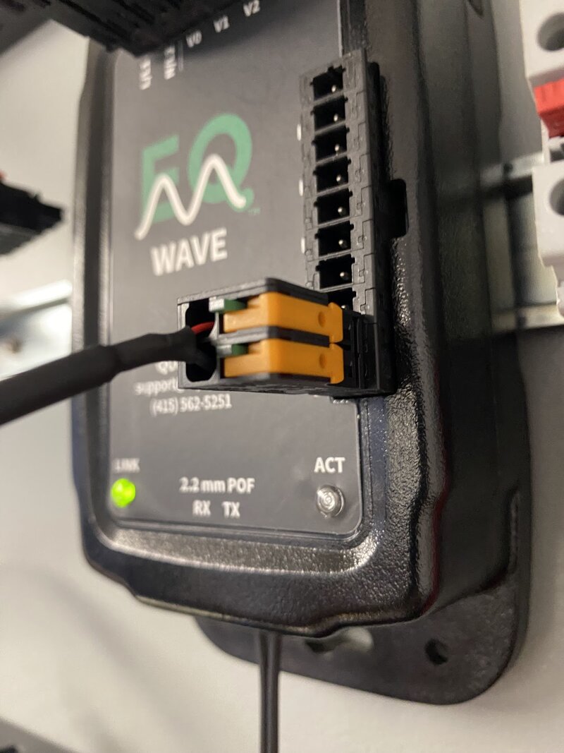
USB power cable connected to DC input for benchtop testing
The included USB power cable provides a convenient 5V DC source for benchtop testing and configuration without requiring AC mains or an external DC supply. The USB cable connects to the VDC+/VDC- terminals.
Grounding and Bonding
Chassis Ground:
- Connect sensor enclosure to facility earth ground per local electrical code
- Recommended wire: 12 AWG minimum copper conductor
- Verify continuity to main ground bus with multimeter
- Proper grounding ensures optimal signal quality and noise immunity
Signal Grounds:
- All measurement circuits are isolated from chassis
- VDC− is the sensor’s system signal ground, not just the return for the DC power option. It is the reference for the entire low-voltage section, including the current inputs. Bond it to earth whether the sensor is AC- or DC-powered; on AC-powered units it is the same terminal, on the current-input connector.
- Avoid ground loops through current sensor shields
No ground leakage from the voltage inputs:
Most power quality meters reference their voltage inputs to their own chassis ground, which is bonded to earth. Their input dividers are therefore a permanent resistive path from each measured phase to earth, and that path is a condition of their safe operation — the instrument depends on its reference staying near earth potential.
The EQ Wave does not work this way. The voltage dividers reference V0 only, and the whole voltage section sits behind a galvanic barrier. Unless you deliberately connect V0 to earth, there is no resistive path from any measured conductor to earth through this sensor — only the barrier’s capacitance, on the order of picofarads.
Two things follow, and both matter more in ungrounded and impedance-grounded systems than in solidly grounded ones:
- The sensor does not inject measurement current into the earth system, and does not appear in the facility’s leakage or hazard-current budget.
- The sensor cannot partially ground a system that was deliberately left ungrounded. See Choosing the V0 Reference for the earth-referenced case, where this is traded away on purpose in exchange for ground-fault visibility.
LED Status Indicators:
After applying power, observe the LED indicators on the device enclosure. The red and green indicators report different things: red is startup progress, green is the optical link.
- Startup: Both red LEDs light, then go out within a few seconds
- LINK LED: Turns solid green when fiber optic link is established with endpoint
- ACT LED: Turns solid green when actively transmitting data
- Fault condition: One or both red LEDs remain lit. How many are still lit indicates how far startup got — see Troubleshooting Guide
Step 5: Connect Plastic Optical Fiber (POF)
POF Cable Preparation (if not supplied with pre-installed connectors):
- Cut cable end: Use the supplied POF cutting tool to make a clean, perpendicular cut
- Separate duplex fibers: Split the webbing 10–15mm from the cut end to separate the two fiber strands
- Verify clean ends: Inspect fiber ends; cuts must be smooth and perpendicular, free from debris
Connect to EQ Wave Device:
- Unlock OptoLock® connector (Firecomms): Pull retainer clip outward to open position
- Insert fiber strands: Push both prepared fiber ends fully into the OptoLock receptacle until seated
- Lock connector: Press retainer clip back to closed position to secure fibers
- Verify insertion: Fibers should be firmly held and not pull out with gentle tugging
Route POF Cable:
- Route cable from sensor location (inside electrical panel) to media converter location (typically outside panel), up to 100 m
- Minimum bend radius: 25mm (do not create sharp bends or kinks)
- Avoid routing near sharp edges that could damage fiber
- Secure cable with tie-wraps or cable clamps every 300–500mm along routing path
Connect to Media Converter:
- Repeat OptoLock connection procedure at media converter end
- Match transmit/receive fibers (if devices are powered, illuminated fiber connects to dark port, dark fiber to illuminated port)
Power Media Converter:
- Recommended (simpler): Connect media converter USB power cable to EQ Gateway USB port
- Alternative: Connect to included USB power supply and plug into mains power
Verify Optical Link:
After connecting fiber and powering media converter:
- EQ Wave sensor: LINK LED turns solid green, ACT LED turns green when data transfer is active
- Media converter: Both amber and green LEDs illuminated
- If link does not establish, see Troubleshooting section
Close Electrical Panel:
Once LED status confirms successful link establishment, reinstall panel cover and secure per local electrical code requirements.
Data Access and Configuration
With EQ Coherence (Recommended)
EQ Coherence records all data locally and provides REST API and WebSocket access. EQ Sight provides real-time visualization of waveforms, power metrics, and harmonics. Data can be exported using the equser Python package. Additional protocol support for SCADA/BMS integration is available upon request.
Setup: Refer to the Gateway Overview for setup procedures.
Direct Network Access (Advanced Integration)
For custom applications requiring direct sensor communication:
Network Configuration:
- IP address: 192.168.10.10 (fixed)
- Subnet: 255.255.255.0
- Connect to sensor network via media converter and Ethernet
Data Protocols:
- CPOW: TCP port 1534 — real-time high-resolution waveform streaming
- Metrics: TCP port 1535 — 10 or 12 cycle aggregated measurements
Documentation:
- API specifications and programming examples available from support@eq.systems
- See Data Access Guide for protocol details and sample code
Verification Checklist
After completing installation, verify system operation through EQ Sight or direct network access.
Physical Installation Verification
- Device securely mounted with adequate clearance (25mm minimum all sides)
- All voltage and current measurement wires fully seated in push-in connectors
- Power connection secure (AC or DC, not both)
- POF cable connected at both ends (sensor and media converter)
- POF cable routing has no sharp bends (25mm minimum radius)
- Terminal identification labels applied for future reference
- Electrical panel cover reinstalled and secured
LED Status Verification
- LINK LED solid green (optical link established)
- ACT LED solid green (sensor active and transmitting data)
- Media converter LEDs illuminated (both amber and green)
Voltage Measurement Verification
- All phase voltages displayed and within ±5% of nominal system voltage
- Phase-to-phase voltages balanced (within 2% of each other for symmetrical systems)
- Phase sequence correct (A→B→C rotation, 120° phase separation for 3-phase systems)
- Voltage reference (V0) reading appropriate for system configuration
Current Measurement Verification
- All phase currents displaying reasonable magnitudes for connected load
- Current magnitudes balanced (within expected range for load configuration)
- Active power (kW) positive for all phases (consuming load) or as expected for generation
- Power factor values reasonable for load type
- Current sensor polarity correct on all phases (reverse polarity if power shows negative for consuming loads)
Network Communication Verification
- Gateway can communicate with sensor (web interface shows live data)
- Data updating in real-time (waveforms refreshing, values changing with load)
- No communication errors or timeout messages
- Network link stable over 5–10 minute observation period
Troubleshooting
For comprehensive troubleshooting beyond installation issues, see the Troubleshooting Guide.
Common Installation Issues
Both LEDs Off - No Power
Symptoms: LEDs completely dark, no startup flash.
Diagnostic Steps:
- Verify power source is energized (measure voltage at source)
- Check terminal connections for proper seating (pull gently to confirm)
- Verify correct power type (AC or DC, not both)
- For AC power: Verify voltage within 85–528V range
- For DC power: Verify voltage within the range for your revision (4.5–48V on v1.3, 4.5–36V on v1.2) and correct polarity
Solutions:
- Verify power supply voltage and re-check terminal connections
- Ensure power source circuit breaker is closed
- For DC power: Verify polarity (VDC+ positive, VDC- negative)
- If power verified at terminals but sensor not operating, contact support@eq.systems
Red LEDs Remain Lit - Fault Condition
Symptoms: One or both red LEDs are still lit a minute after power-on. On a healthy unit they light at power-on and go out within a few seconds. How many remain lit indicates how far startup got — see the Troubleshooting Guide for the LED reference.
The pluggable terminal blocks have no breaking capacity (COC per IEC 61984). They must never be engaged or disengaged while energized or under load. De-energize the circuit per lockout/tagout before removing or fitting any plug — including when cycling power or isolating a fault.
Diagnostic Steps:
- Check all measurement input connections for proper seating (visual only — do not unplug)
- Verify no short circuits or over-voltage conditions on measurement inputs
- De-energize per lockout/tagout, wait 10 seconds, then re-energize
- Check for visible damage to sensor enclosure or terminals
Solutions:
- Verify all terminal connections are fully seated
- To isolate the fault, de-energize per lockout/tagout, then disconnect measurement inputs
- If fault persists with no connections, contact support@eq.systems for RMA
LEDs Not Green - No Optical Link
Symptoms: ACT LED solid green, but LINK LED not solid green.
Diagnostic Steps:
- Verify media converter has power (LEDs illuminated)
- Check POF cable connections at both ends (sensor and media converter)
- Inspect fiber ends for contamination or damage
- Verify cable routing has no sharp bends or pinch points
Solutions:
- Remove and reconnect POF cable at both ends, ensure full insertion
- Clean fiber ends with isopropyl alcohol if contaminated
- Re-cut fiber ends if damaged or poorly prepared
- Try swapping transmit/receive fibers at media converter
- If link cannot be established, refer to EQ Gateway troubleshooting documentation or contact support@eq.systems
Negative Power Readings - Current Sensor Polarity Reversed
Symptoms: Active power (kW) shows negative for consuming loads on one or more phases.
Solutions:
- Recommended: Correct polarity via EQ Gateway software configuration (no rewiring required)
- Alternative: Physically reverse current sensor connections for affected phase (swap + and - terminals)
Incorrect Phase Sequence
Symptoms: Phase rotation displays as A→C→B instead of A→B→C, or phases are misidentified.
Solutions:
- Recommended: Correct phase mapping via EQ Gateway software configuration
- Alternative: Verify and correct voltage input wiring to match actual system phases
Technical Specifications
For complete technical specifications, see the EQ Wave v1 Datasheet (PDF).